Wiring the Car
Electric fan relay update April 30, 2020
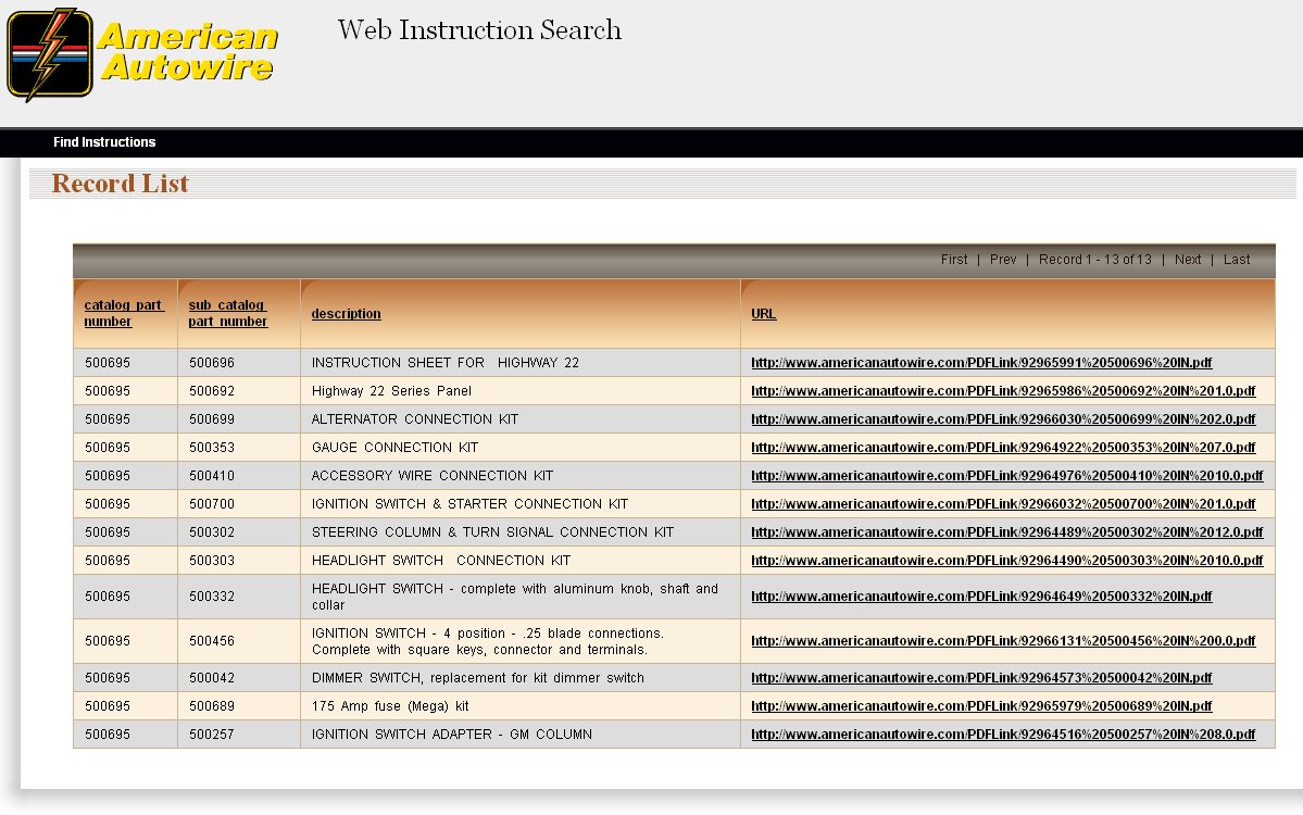
One of the earlier items that I purchased (2007) was an American Autowire Highway 22 wiring kit from Hot Rods USA. As the name implies, it includes 22 different circuits. This is sort of the cadillac of wiring kits and will more than fill my needs. I did not expect it would take me 5 years before I got around to installing it, but it cost considerably less than if I were to buy it today .
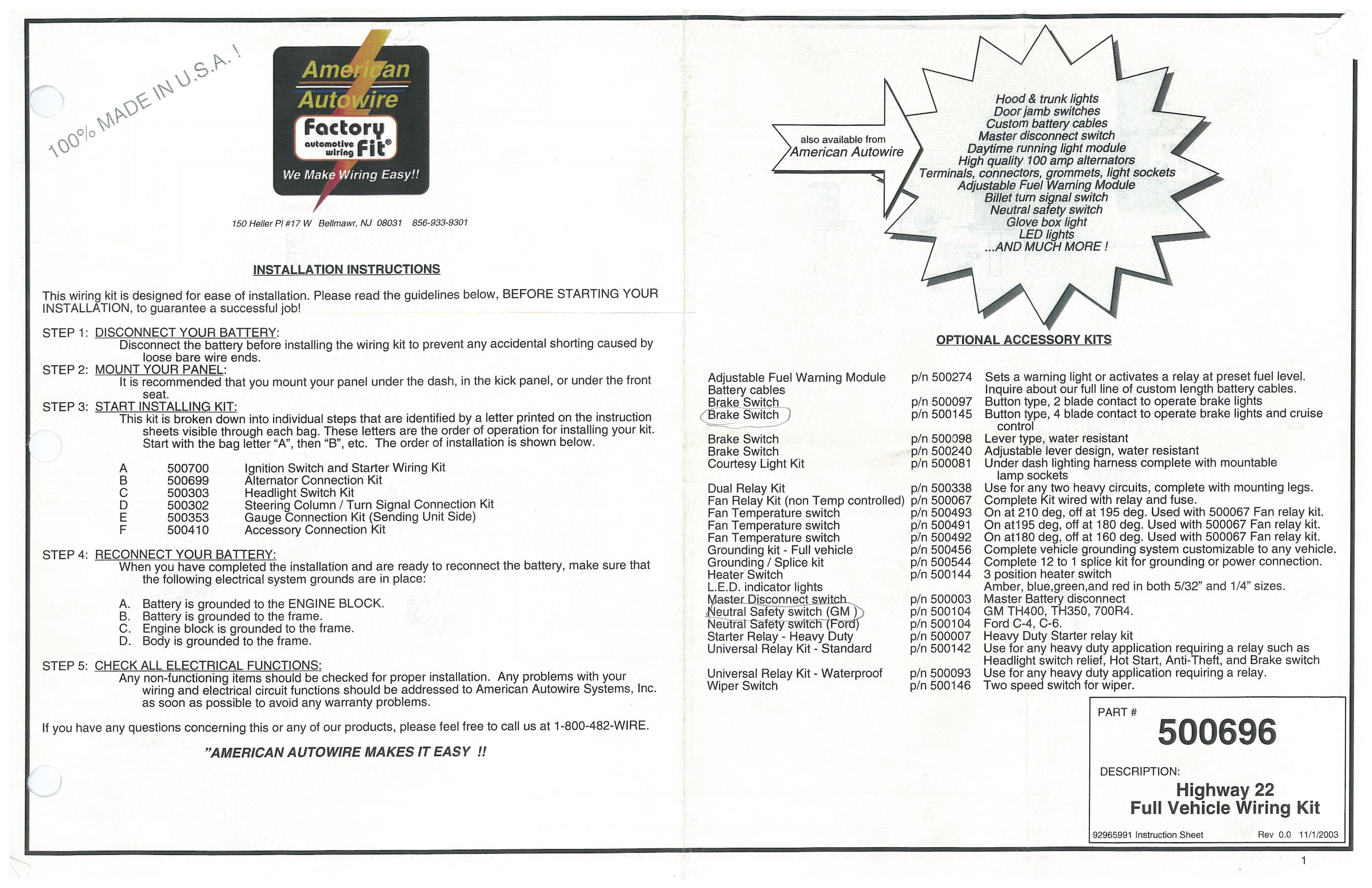
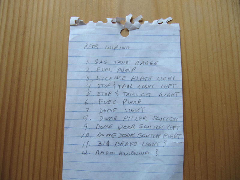
The kit came in several individual bags whose function is listed in the photo below. It included a light switch and ignition switch which I keyed to a late forties GM style key. Each wire in the kit is labeled every foot with it's specific function.
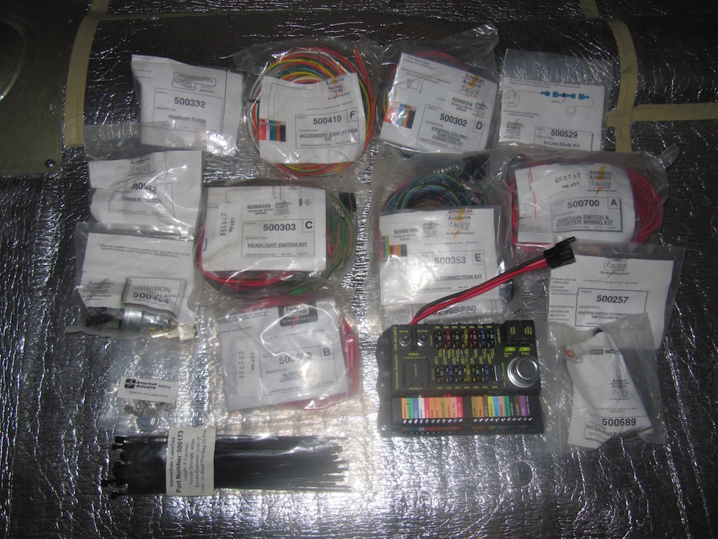
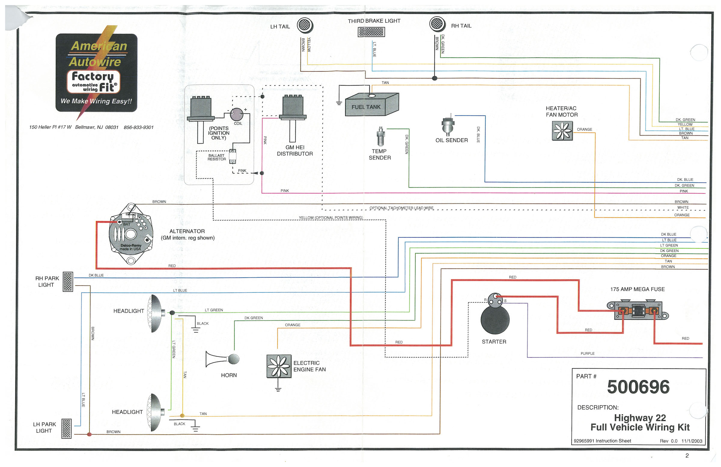
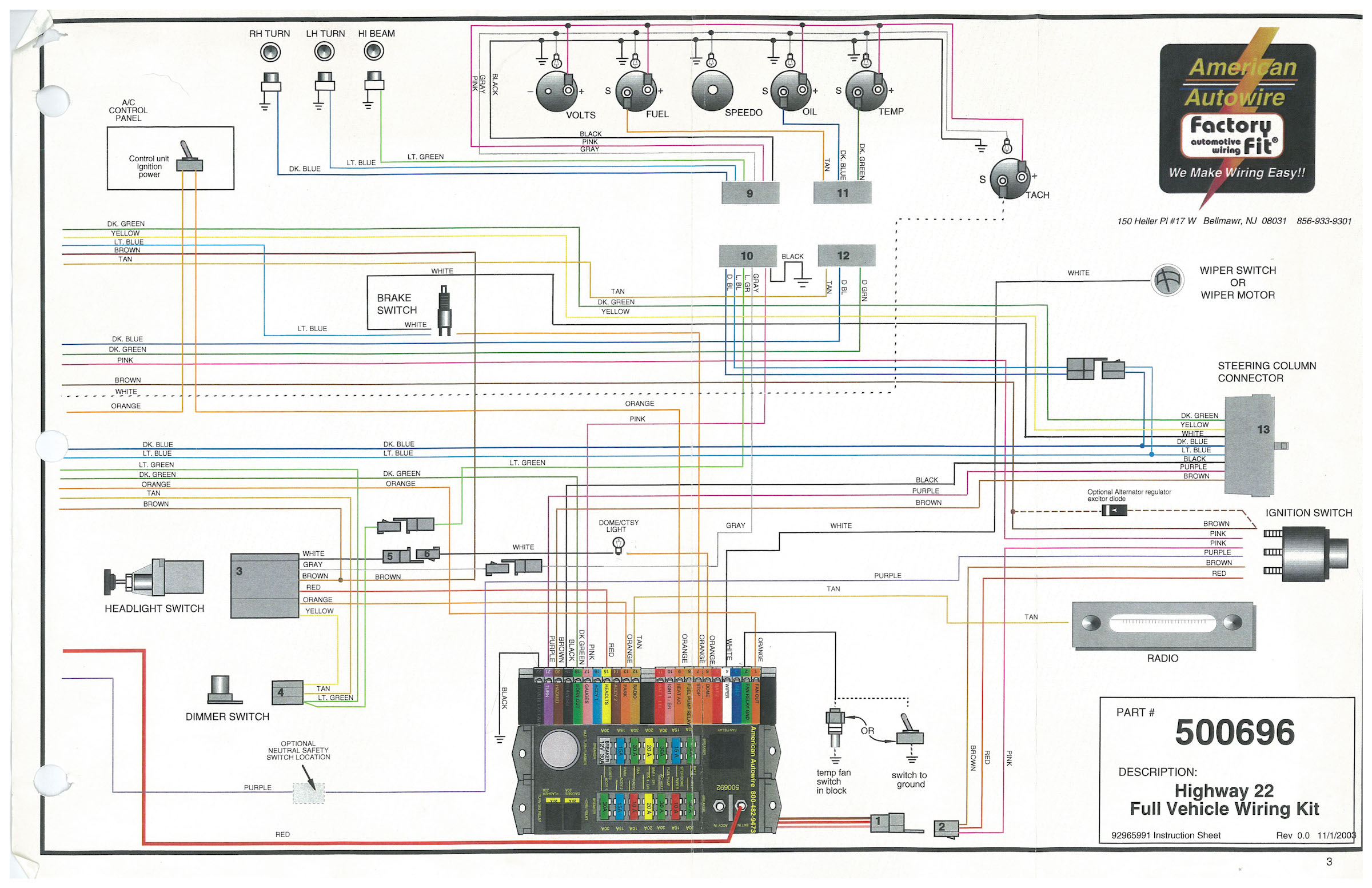
The 3 pictures below show the main layout of the wiring diagram. In addition, each plastic bag contained wiring circuit diagrams for that particular item.
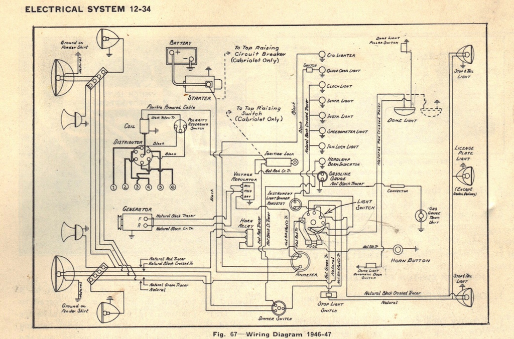
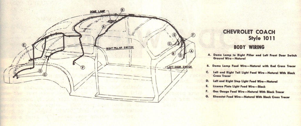
The picture below shows the original wiring diagram for my 1947 Chevrolet Fleetmaster.
The picture below shows the wire routing diagram. I pretty well followed this diagram when I ran the new wires. In this diagram, the door dome switch is on the driver's side, while my original switch is on the passenger side (ended up using both sides).
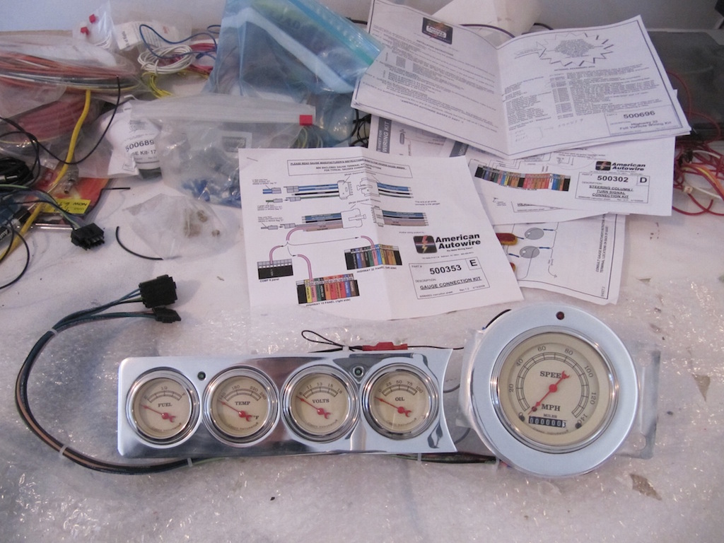
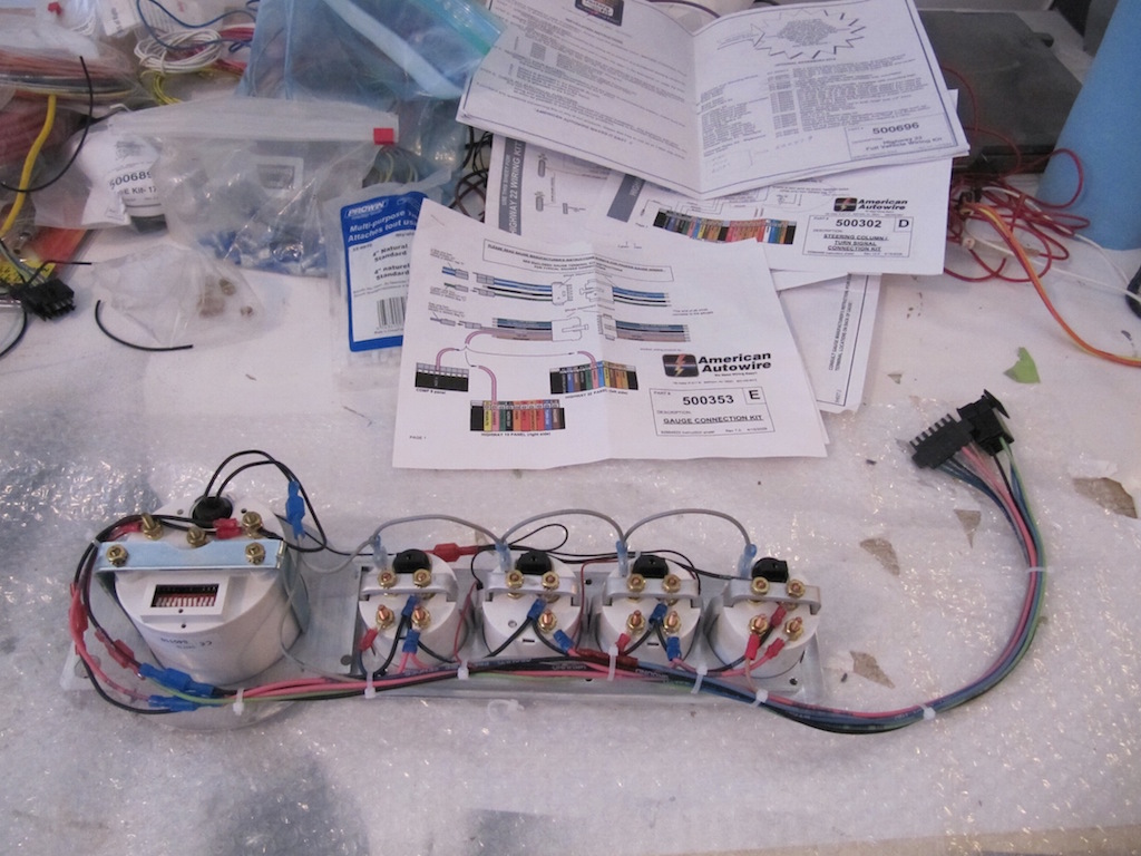
In June 2010, Jill and I went to the Minneapolis Back-to-the-Fifties car show with another couple. Besides viewing the 11,000 street rods, I got to make some timely purchases at the various booths that were set up. I had already decided that I wanted the Classic Instruments Vintage series gauges for my dash.
I had already purchased the chrome dash insert from Chevs-of-the-forties. I first checked out the Classic Instrument booth to see what the ballpark price was for that particular kit. I then went to the Gearhead World booth to see if they had the kit. They didn't have it in stock but if I waited10 minutes they could get it for $150.00 less than the Classic Instrument booth price. They proceeded to walk down to the Classic booth, got the kit, walked back and sold it to me.
It was a great deal.
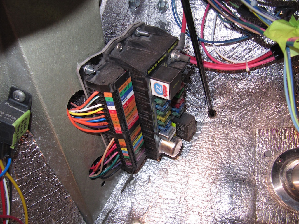
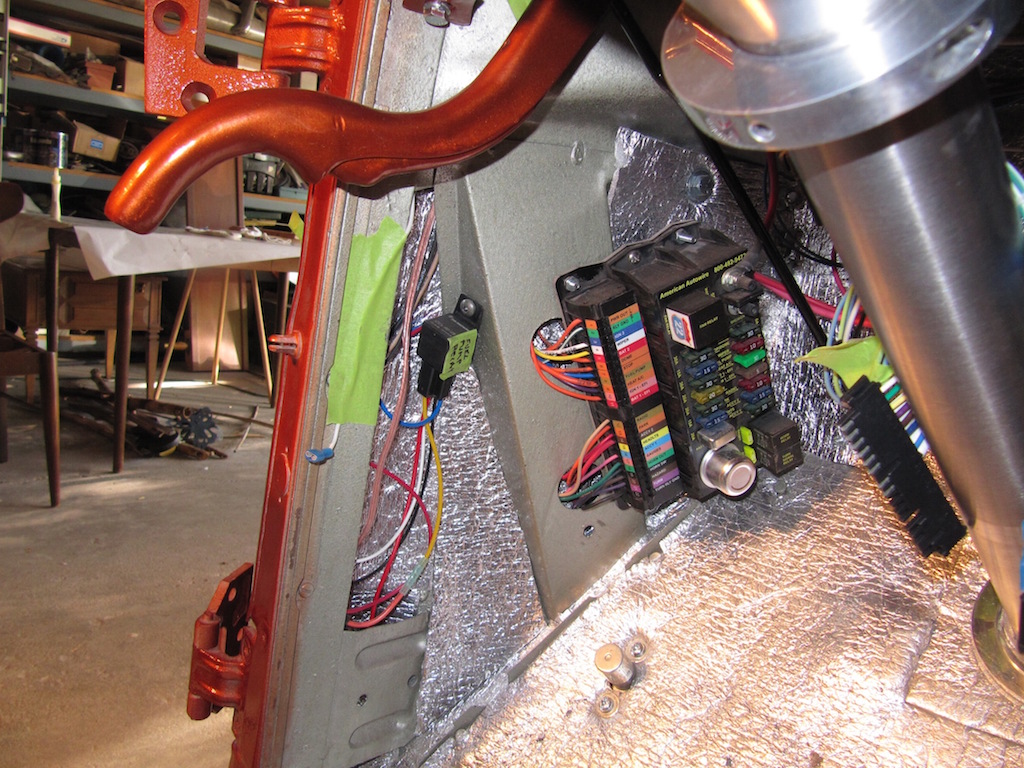
The relay to the left of the fuse panel is the fuel pump relay.
Update 11/15/2014: I installed the driver's side door switch. I moved the fuel pump relay slightly and installed a speaker for the radio just below it.
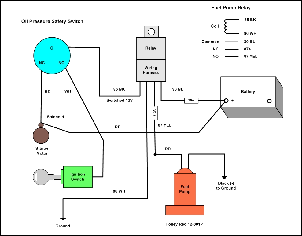
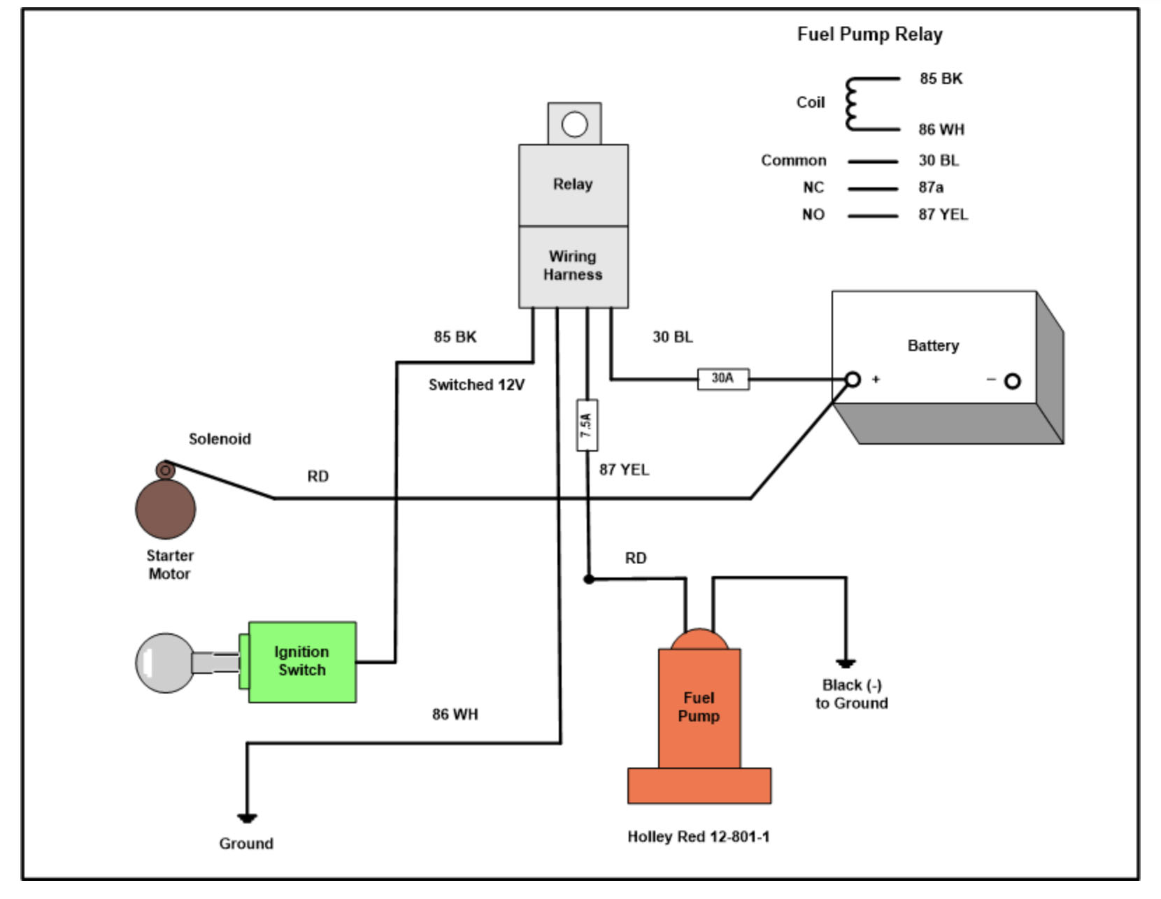
The picture above is a redrawing of the wiring diagram for the Holley fuel pump and oil pressure safety switch (using Microsoft Visio). I redid it to include the modifications for the Autowire Highway 22 wiring kit. The 30 amp fuse is in the fuse panel and the 7.5 amp fuse is an in-line connection for added safety .
Update 11/15/2014: I removed the oil pressure safety switch from the circuit.
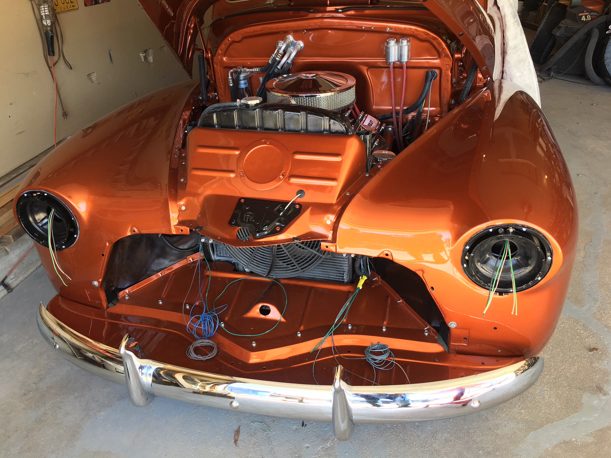
The picture above shows the headlight wiring. Next up is wiring for the horn, then mounting the grill in order to finish the park and turning signal lights (which are mounted in the grill). The original wiring attached to the top of the radiator, but I didn't like the look so I ran it at the bottom and hidden.
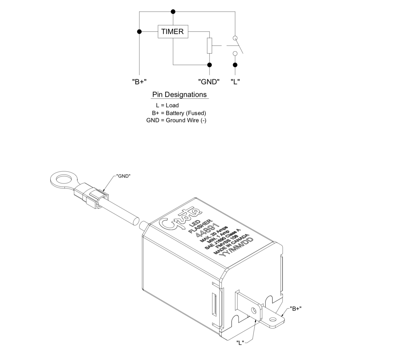
Since I changed the tail lights to LEDs, I had to change the turn signal/hazard relay to handle the load. I used a Grate # 4489-1 relay.

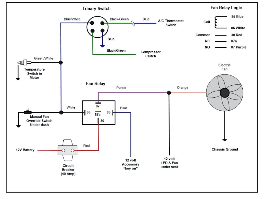
Electric fan relay update April 30, 2020:
I added a small 12 volt computer fan with color LED lights below the driver's seat so that I could tell when the radiator pusher fan operated. The fan's 40 amp circuit breaker was mounted too close to the exhaust manifold and the thermo breaker was operating without my knowledge and shutting down the fan. As a result the car was overheating.
I drew the circuit out below using Microsoft Visio: